

Thermocouple Wire (TX, JX, EX, NX, NC, KX, KCB, KCA, SC or RC)
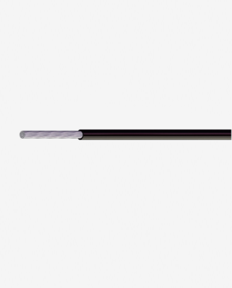
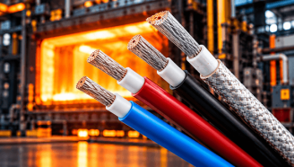
Thermocouple wire (TX, JX, EX, NX, NC, KX, KCB, KCA, SC, RC) is a specialized alloy thermocouple compensation and extension cable. It is available with PVC, PTFE, silicone rubber or glass fiber insulation and sheath, with optional shielding. Rated 300V/600V, it covers a wide working temperature range from -65°C up to 1000°C and offers good radiation resistance. It meets flame propagation standards and is RoHS compliant. It is widely used for thermocouple signal transmission, temperature measurement compensation, BMS internal wiring and charging connection wiring.
23 people are viewing this right now
- Extreme Performance : Built for demanding environments.
- Certified Quality : Built to meet industry standards.
- Custom Cable Solutions : Tailored to your requirements.
- Technical Support : info@voltaracable.com
Product Structures
- Conductor: Solid or stranded alloy wire(s). Properties per GB/T4989-1994.
- Insulation: PVC, PTFE, Silicone Rubber, Glass Fiber
- Shielding: Optional
- Sheath: PVC, PTFE, Silicone Rubber, Glass Fiber
Technical data
- Temperature range: -65~+1000°C
- Rated voltage: U0/U 300V/600V
- Test voltage: 1500V/2000V
- Insulation resistance: ≥ 100MΩ·km at 20°C
- Radiation resistance: PVC: up to 80×10⁴J/kg (up to 80Mrad) Teflon: up to 1×10⁵J/kg (up to 1 Mrad) Silicone Rubber: up to 20×10⁴J/kg (up to 20Mrad)
Product Features
- Flame Propagation Performance: Compliant with DIN VDE 0482-332-1-2, DIN EN 60332-1-2, IEC 60332-1 (No flame propagation in fire).
- Free of hazardous substances, compliant with ROHS standard.
Applications
- Thermocouple Compensation/Extension Wires: A pair of insulated wires matching the nominal thermoelectric EMF (electromotive force) of specific thermocouple types within defined temperature ranges (including ambient). Used to connect thermocouples to measuring instruments, compensating for temperature errors induced at connection points. (Types: Compensation Grade (e.g., TX, JX) or Extension Grade (e.g., KX, EX).
- Battery Pack Systems: Internal wiring for BMS (Battery Management Systems).
- Charging Interfaces: Wiring between charging ports and battery packs or chargers.
Technical Parameters:
| Type | Item | Matching Thermocouple Type | Thermocouple Designation | Product Model Code Interpretation |
|---|---|---|---|---|
| SC or RC | Copper-Constantan Compensation Grade Thermocouple Wire 0.6mm² | Platinum Rhodium 10%-Platinum Thermocouple Platinum Rhodium 13%-Platinum Thermocouple |
S or R | S: Special tolerance grade (Precision compensation wire per IEC 60584-3) P: Shielded compensation wire (With metallic braid shielding layer) G: General-purpose compensation wire (Standard industrial applications) V: Polyvinyl Chloride (PVC) insulation/sheath H: Heat-resistant compensation wire (For high-temperature service) F: Polytetrafluoroethylene (PTFE) insulation/sheath R: Stranded conductor (Flexible multi-core construction) B: Alkali-free glass fiber insulation (Continuous operating temp. up to 450°C) |
| KCA KCB KX |
Iron-Constantan 22mm² Compensation Grade Wire Copper-Constantan 40mm² Compensation Grade Wire Copper-Constantan 10- Copper 3 extended wire |
Nickel Chromium-Nickel Silicon Thermocouple | K | |
| NC NX |
Iron-copper-nickel 18 compensating wire Nickel-chromium 14 – nickel-silicon extended wire |
Nickel Chromium-Nickel Silicon Thermocouple | N | |
| EX | Nickel-chromium 10 – copper 45 extended wire | Nickel Chromium-Nickel Thermocouple | E | |
| JX | Iron-copper-nickel 45 extended wire | Iron-copper-nickel thermocouple | J | |
| TX | Copper-copper-nickel 45 continuous wire | Copper-nickel thermocouple | T |
| Conductor type | Conductor nominal cross-sectional area (mm²) | Number of conductor strands | Linear density of alloy wire (mm) |
|---|---|---|---|
| Single-strand conductor | 0.2 | 1 | 0.52 |
| 0.5 | 1 | 0.80 | |
| 1.0 | 1 | 1.13 | |
| 1.5 | 1 | 1.37 | |
| 2.5 | 1 | 1.76 | |
| Multi-strand conductor (flexible cord) | 0.2 | 7 | 0.20 |
| 0.5 | 7 | 0.30 | |
| 1.0 | 7 | 0.43 | |
| 1.5 | 7 | 0.52 | |
| 2.5 | 19 | 0.41 |
| Use categories | Conductor nominal cross-sectional area (mm²) | Nominal thickness of insulation layer (mm) | Nominal thickness of sheath (mm) | Maximum Outer Diameter of Reinforced Conductor (mm) | |
|---|---|---|---|---|---|
| Single-strand conductor | Multi-strand conductor | ||||
| Generally used | 0.2 | 0.4 | 0.7 | 3.0×4.6 | 3.1×4.8 |
| 0.5 | 0.4 | 0.8 | 3.7×6.0 | 3.9×6.6 | |
| 1.0 | 0.7 | 1.0 | 5.0×7.7 | 5.1×8.0 | |
| 1.5 | 0.7 | 1.0 | 5.2×8.3 | 5.5×8.2 | |
| 2.5 | 0.7 | 1.0 | 5.7×9.3 | 5.9×9.8 | |
| Heat resistant | 0.2 | 0.4 | 0.3 | 2.3×4.0 | 2.4×4.2 |
| 0.5 | 0.4 | 0.3 | 2.6×4.6 | 2.8×4.8 | |
| 1.0 | 0.4 | 0.3 | 3.0×5.3 | 3.1×5.6 | |
| 1.5 | 0.4 | 0.3 | 3.2×5.8 | 3.4×6.2 | |
| 2.5 | 0.4 | 0.3 | 3.6×6.7 | 4.0×7.3 | |